

Post by sc397 on Oct 12, 2016 9:12:16 GMT -8
Someone asked me to post up how I install the internal oil line so, here goes.
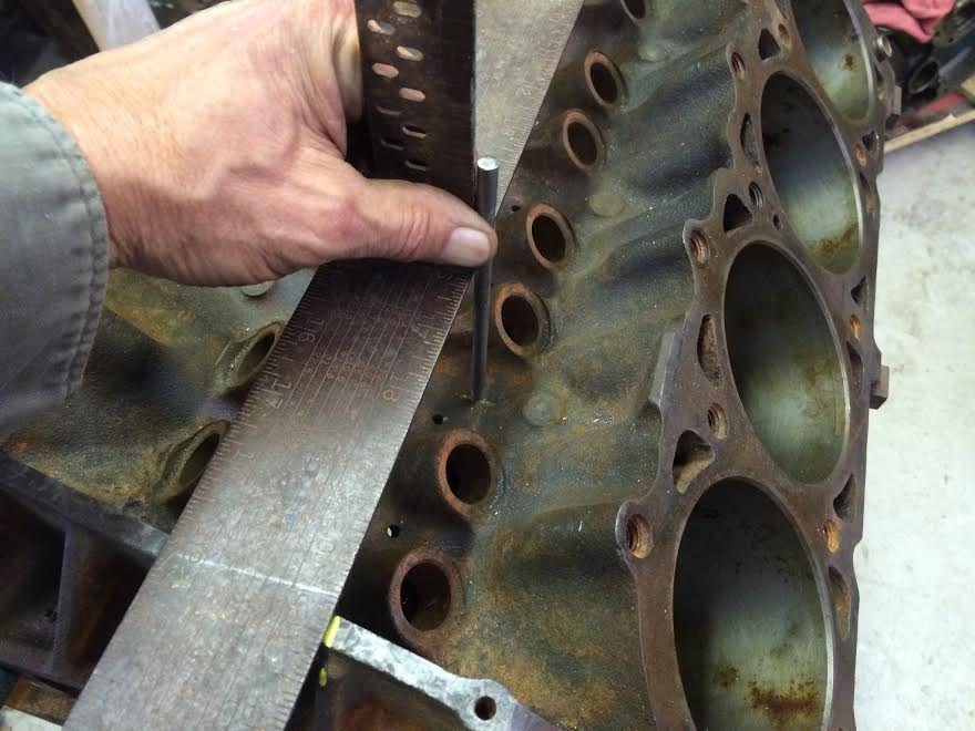
First thing I do is stick a 1/2" rod in the cross-over hole in the front to use as a guide to mark where to drill in the front.
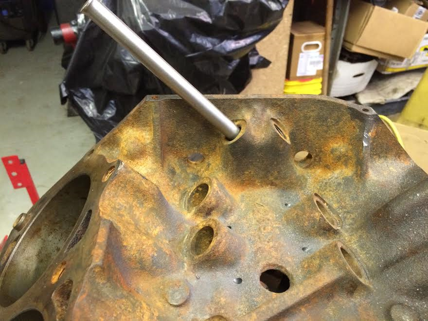
Then I sight down the rod and mark the block.
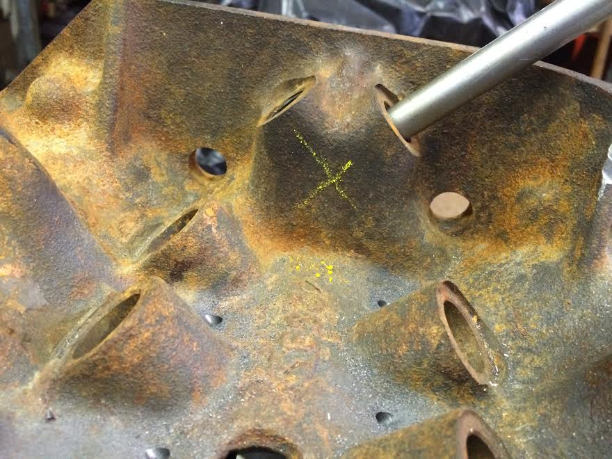
I do the other side and end up with a X that marks the spot for the hole.
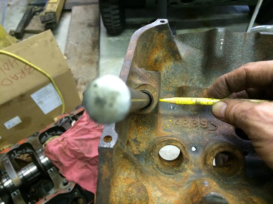
Then I mark a line centered up between the two lifter bores closest to the 4th main bearing oil feed hole back.
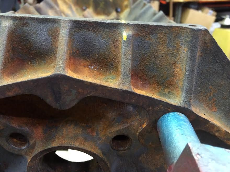
To find the center of the oil galley in front I mark on the top of the block so that I can lay a streight edge across.
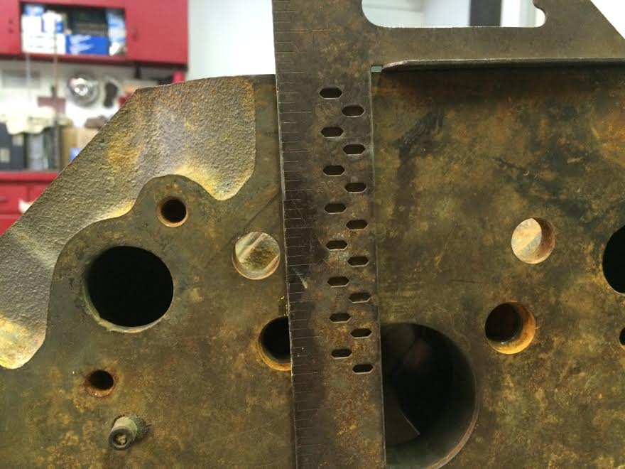
I mark the top at the rear which is basically on the left side of the reinforcement rib as shown.
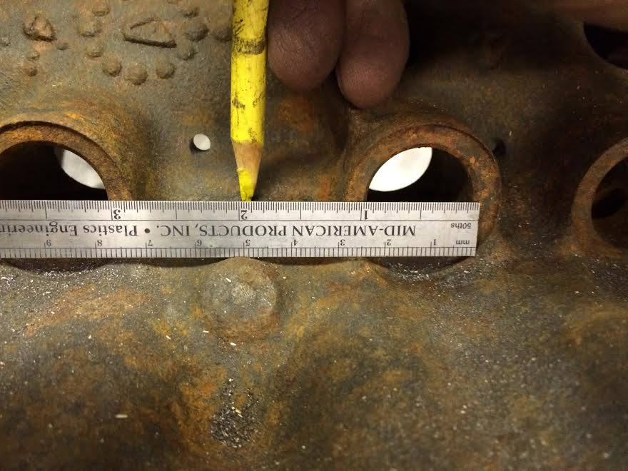
I lay a streight edge across the two markes and move it away 1/2 of the punch diameter. I square it up with a small square and center punch where the hole needs to go.
After center punching I drill the holes with incremental sizes 3/16", 3/8" and 7/16".
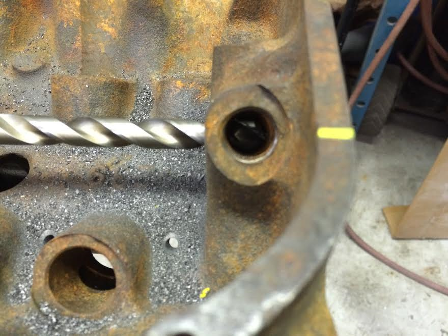
You can see the main bearing oil hole that we are trying to direct feed in this picture.
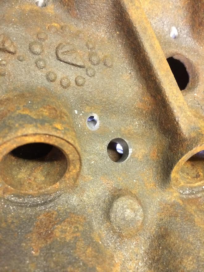
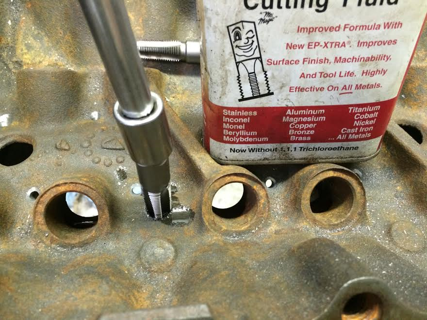
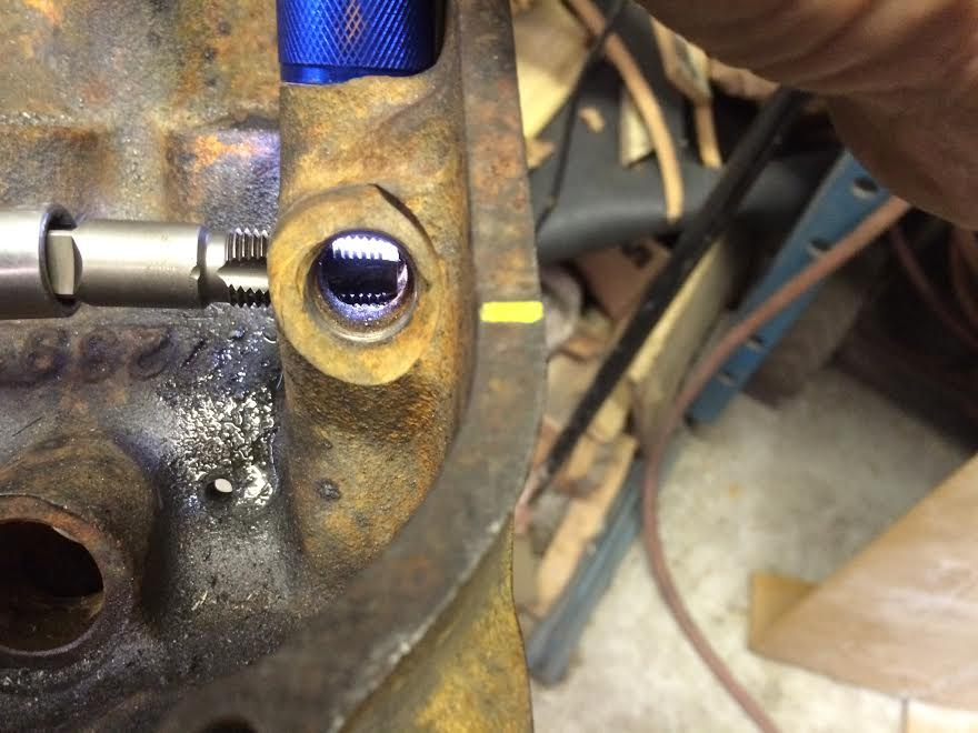
I tap the oil holes to 1/4 NPT which calls for a 7/16" Tap Drill. I can never seem to tap that size hole with over the counter pipe taps so, I drill it out to .465" dia. I run the tap in until it bottoms out. This works pretty good because the fittings go in to just the right depth.
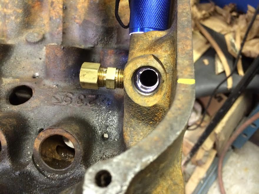
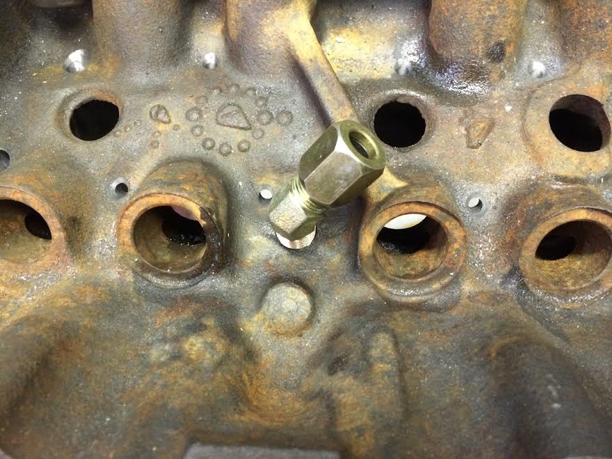
I use 1/4"pipe x 3/8"tube compression fittings for the line. You can see in this picture that the fitting is tight and does not restrict the oil passage in the block. This is exactly what I want.
I use a 45 degree angled fitting in the lifter galley. Just like the front fitting, it does not restrict the oil flow through the lifter oil galley.
 IMG_4028 by Rick Jones, on Flickr
 IMG_4030 by Rick Jones, on Flickr
Continued..
Here is some information in regard to the difference in crank shaft oil holes.
theamcforum.com/forum/390-cranks_topic67162_page1.html
First thing I do is stick a 1/2" rod in the cross-over hole in the front to use as a guide to mark where to drill in the front.

Then I sight down the rod and mark the block.

I do the other side and end up with a X that marks the spot for the hole.

Then I mark a line centered up between the two lifter bores closest to the 4th main bearing oil feed hole back.

To find the center of the oil galley in front I mark on the top of the block so that I can lay a streight edge across.

I mark the top at the rear which is basically on the left side of the reinforcement rib as shown.

I lay a streight edge across the two markes and move it away 1/2 of the punch diameter. I square it up with a small square and center punch where the hole needs to go.

After center punching I drill the holes with incremental sizes 3/16", 3/8" and 7/16".

You can see the main bearing oil hole that we are trying to direct feed in this picture.

I tap the oil holes to 1/4 NPT which calls for a 7/16" Tap Drill. I can never seem to tap that size hole with over the counter pipe taps so, I drill it out to .465" dia. I run the tap in until it bottoms out. This works pretty good because the fittings go in to just the right depth.


I use 1/4"pipe x 3/8"tube compression fittings for the line. You can see in this picture that the fitting is tight and does not restrict the oil passage in the block. This is exactly what I want.

I use a 45 degree angled fitting in the lifter galley. Just like the front fitting, it does not restrict the oil flow through the lifter oil galley.
 IMG_4028 by Rick Jones, on FlickrIMG_4030 by Rick Jones, on Flickr
Continued..
Here is some information in regard to the difference in crank shaft oil holes.
theamcforum.com/forum/390-cranks_topic67162_page1.html
